HOWE TRUSS
For a project in my engineering class, I was tasked with designing a specific type of
truss which would have a force applied directly on top of it. The truss I was tasked with
designing was a Howe truss with a maximum of 11 nodes. I designed this truss using
the John Hopkins Truss Simulator App provided to us in class. The Truss simulator app
provided information about the force in each member and whether that force was
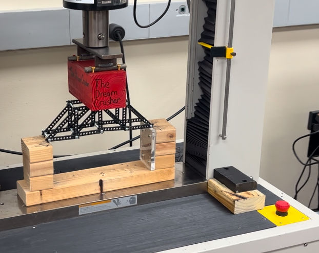
tension or compression. I then built the truss using the plastic bars, screws, and bolts
provided to us in class. Finally we loaded our truss to failure in the lab using an MTS QTEST 100 electro-mechanical tension and compression testing machine. The way the truss was loaded in the machine was
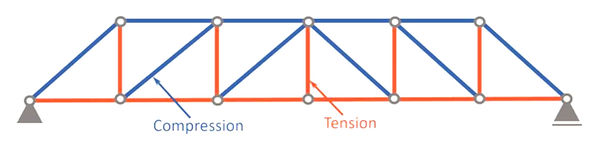
not optimal as a Howe truss when loaded on the top chord results in a zero force vertical
member in the middle of the span, which would not be the case if the truss was loaded along
the bottom chord, as it would be in a typical bridge structure. This project taught me about force
distributions in a truss system and exposed me to mechanical testing of structural systems.
If the Howe truss were loaded along the bottom chord as it is intended to be, the nature (tension
and compression) of the force in the members would look like as follows.